Impedance Stabilization Networks (ISN) for All EMC Test Environments
RF HV-AN & ISN
TESEQ offers a comprehensive selection of Line Impedance Stabilization Networks (LISNs/AMN/ISN/AAN) specifically designed to measure conducted common mode disturbances on ITE(International Technology Equipment) in accordance with CISPR22 and CISPR32.
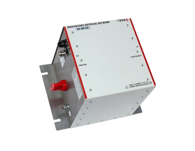
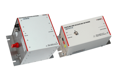
Teseq’s artificial network HV-AN 150 is the first universal solution which covers several applications and standards in the Automotive, Airborne and MIL range. It offers the right solution for both high current and high voltage EUTs and can be housed for having a shielded box, see option SME HV-AN 150, as proposed in CISPR 12 (draft), CISPR 25, ECE No. 10 R05 / 06, ISO 11452-1 and ISO / DTS 7637-4.
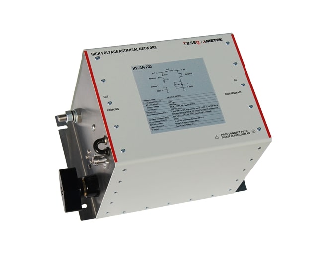
The artificial network HV-AN 200 offers a solution for high current and high voltage connections to the EUTs. The AN is used to simulate the impedance of a vehicle harness to determine the behavior of EUT and meet the requirements of ISO 7637-2 and the HV part of CISPR 12 (draft), CISPR 25, ECE No. 10 R05 / 06, ISO 11452-1 and ISO / DTS 7637-4.
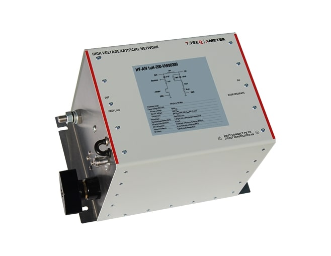
The artificial network HV-AN 1uH-200-VW80300 offers a solution for high current and high voltage connections to the EUTs as proposed in VW 80300. The AN is used to simulate the impedance of a vehicle harness to determine the behavior of EUT.
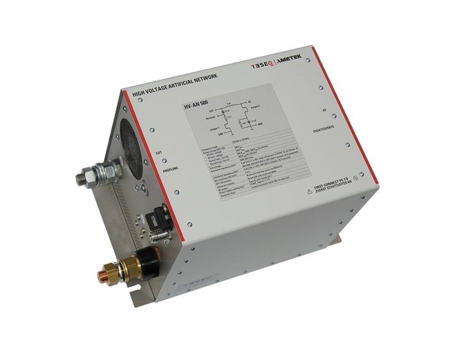
The artificial network HV-AN 500 offers a solution for high current and high voltage connections to the EUTs. The AN is used to simulate the impedance of a vehicle harness to determine the behavior of EUT and meet the requirements of ISO 7637-2 and the HV part of CISPR 12 (draft), CISPR 25, ECE No. 10 R05 / 06, ISO 11452-1 and ISO / DTS 7637-4. The optional available HV-AN 500-option-1μF, connected on the AE port of the HV-AN 500, allows testing of the LV part of CISPR 25, ECE No. 10 R06 and ISO 11452-1.
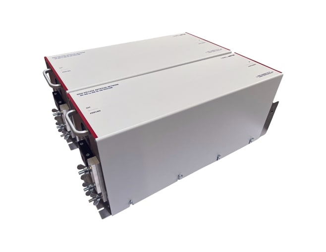
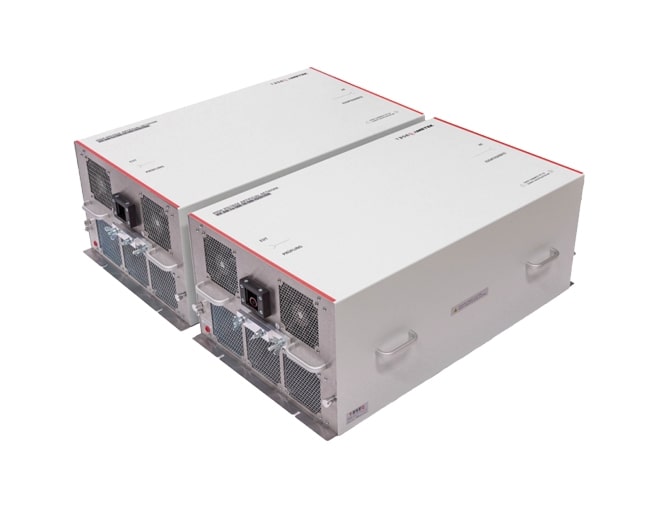
The HV-AN 1u-250 ISO 21498 are artificial networks used for electric vehicle high voltage component tests up to 250 ADC. The AN simulates the impedance of a vehicle harness and battery and is used for emission measurements. It meets the requirements of ISO 21498-2, MBN 11123, BMW GS95023 and similar standards. The HV-AN 1u-ISO 21498 is based on a modular concept. Each module incorporates the 1 uH inductance, 1 uF capacitor and one resistance value. A pair of two HV-AN 1u-ISO21498 forms a complete set for HV+ and HV- supply lines to high voltage components. Separate sets are available for each resistance value and EUT current.
The HV-AN 1u-500 ISO 21498 are artificial networks used for electric vehicle high voltage component tests up to 500 ADC. The AN simulates the impedance of a vehicle harness and battery and is used for emission measurements. It meets the requirements of ISO 21498-2, MBN 11123, BMW GS95023 and similar standards. The HV-AN 1u-ISO 21498 is based on a modular concept. Each module incorporates the 1 uH inductance, 1 uF capacitor and one resistance value. A pair of two HV-AN 1u-ISO21498 forms a complete set for HV+ and HV- supply lines to high voltage components. Separate sets are available for each resistance value and EUT current.
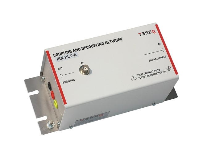
The ISN PLT-A is made for measurements on PLT devices which use one port for mains power supply and telecommunications (PLT port). It is conform with the requirements of EN 50561-1. Included in the delivery is the Coupling Unit (CU) as given in figure 3 of the standard.
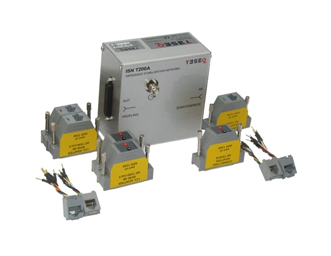
Impedance stabilization networks (ISN, or with CISPR 16-1-2 called AAN: asymmetric artificial network) are defined for measuring of conducted common mode disturbances at information technology equipment (ITE) as required in CISPR 22 and CISPR 32. The ISN is placed between the equipment under test (EUT) and auxiliary equipment (AE) or load which are necessary for the operation of the EUT. The ISN establishes the common-mode termination impedance for the EUT’s telecommunications port during measurement and emulates the unsymmetrical contribution (longitudinal conversion loss, LCL) of the connected line. Different ISNs are available in relation to the line category, line numbers and pin-arrangement. The ISN T2A is designed for measurements on one unscreened balanced pair and consists of one basic network (ISN T200A) with D sub 25 connectors and special adapter sets. A set of adapters consists of LCL adapters to realize the longitudinal conversion loss (LCL)- requirements for the EUT-side in relation to the used cable category (cat. 3, cat. 5) and a connection adapter for the AE-side.
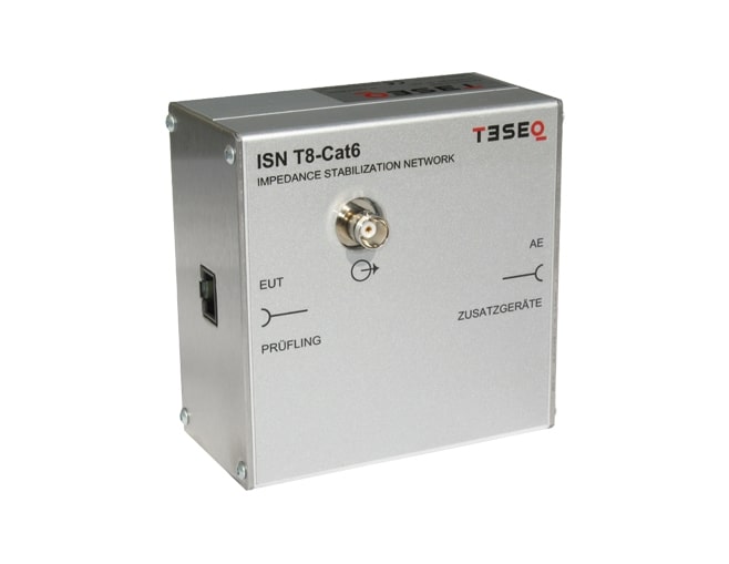
Impedance stabilization networks (ISN, or with CISPR 16-1-2 called AAN: asymmetric artificial network) are defined for measuring of conducted common mode disturbances at information technology equipment (ITE) as required in CISPR 22 and CISPR 32. The ISN is placed between the equipment under test (EUT) and auxiliary equipment (AE) or load which are necessary for the operation of the EUT. The ISN establishes the common-mode termination impedance for the EUT’s telecommunications port during measurement and emulates the unsymmetrical contribution (longitudinal conversion loss, LCL) of the connected line. Different ISNs are available in relation to the line category, line numbers and pin-arrangement. The ISN T8-Cat6 is designed for measurements on up to four unscreened single balanced pairs with cable category cat. 6. It can also be used as CDN for immunity testing according IEC/EN 61000-4-6 up to 80 MHz. The ISN T8-Cat6 is designed for measurements on up to four unscreened single balanced pairs with cable category cat. 6. It can also be used as CDN for immunity testing according IEC/EN 61000-4-6 up to 80 MHz.
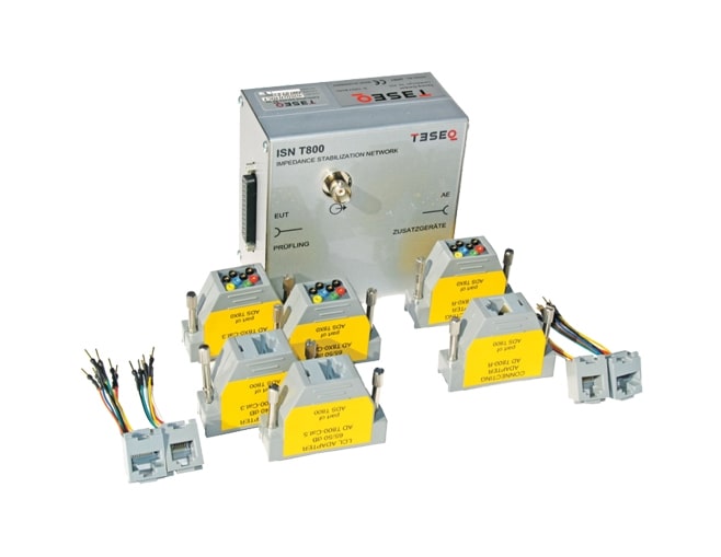
Impedance stabilization networks (ISN, or with CISPR 16-1-2 called AAN: asymmetric artificial network) are defined for measuring of conducted common mode disturbances at information technology equipment (ITE) as required in CISPR 22 and CISPR 32. The ISN is placed between the equipment under test (EUT) and auxiliary equipment (AE) or load which are necessary for the operation of the EUT. The ISN establishes the common-mode termination impedance for the EUT’s telecommunications port during measurement and emulates the unsymmetrical contribution (longitudinal conversion loss, LCL) of the connected line. Different ISNs are available in relation to the line category, line numbers and pin-arrangement. The ISN T8 is designed for measurements on up to four unscreened single balanced pairs and consists of one basic network (ISN T800) with D sub 25 connectors and special adapter sets. A set of adapters consists of two pieces of LCL adapters to arrange the lines and realize longitudinal conversion loss (LCL)- requirements for the EUT-side in relation to the use cable category (cat. 3, cat. 5) and one piece of connection adapter arranges the lines for the AE-side. Teseq offers two different adapter sets – ADS T800 and ADS T8x0. ADS T800 gives the connection to RJ45 sockets with pin-arrangements of EIA/TIA T568A respectively T568B. The adapter set ADS T8x0 offers changeable pin-arrangements via 1 mm banana connectors for each pin combination of RJ11/RJ45. The ISN T8 is designed for measurements on up to four unscreened single balanced pairs and consists of one basic network (ISN T800) with D sub 25 connectors and special adapter sets. A set of adapters consists of two pieces of LCL adapters to arrange the lines and realize longitudinal conversion loss (LCL)- requirements for the EUT-side in relation to the use cable category (cat. 3, cat. 5) and one piece of connection adapter arranges the lines for the AE-side. Teseq offers two different adapter sets – ADS T800 and ADS T8x0. ADS T800 gives the connection to RJ45 sockets with pin-arrangements of EIA/TIA T568A respectively T568B. The adapter set ADS T8x0 offers changeable pin-arrangements via 1 mm banana connectors for each pin combination of RJ11/RJ45.
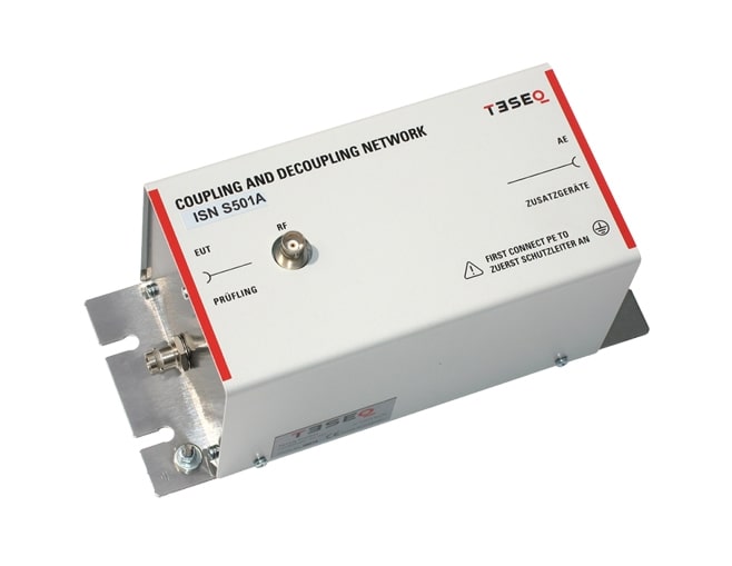
Impedance stabilization networks (ISN, or with CISPR 16-1-2 called AAN: asymmetric artificial network or AN: artificial networks for coaxial and other screened cables) are defined for measuring of conducted common mode disturbances at information technology equipment (ITE) as required in CISPR 22. The ISN is placed between the equipment under test (EUT) and auxiliary equipment (AE) or load which are necessary for the operation of the EUT. The ISN establishes the common-mode termination impedance for the EUT’s telecommunications port during measurement. ISN S501A, ISN S502A, ISN S751 and ISN S752 are designed for measurements on coaxial telecommunication lines. The used internal cable has a impedance of 50 Ω for ISN S501A and ISN S502A or 75 Ω for ISN S751 and ISN S752. The cable screen is connected on the AE side to the ground. ISN S502A and ISN S752 are supplied with double screened coaxial cables and N connector. A design example is given in figure D.9 CISPR 22 (EN 55022) and figure G.9 CISPR 32 (EN 55032).
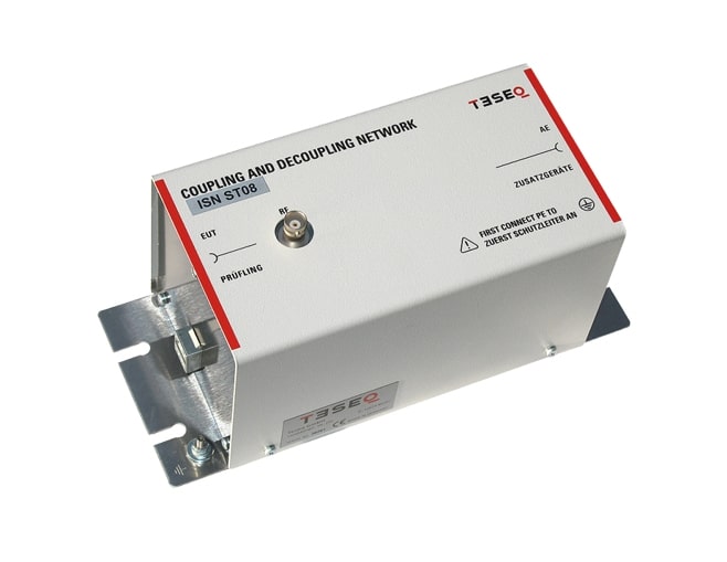
Impedance stabilization networks (ISN, or with CISPR 16-1-2 called AAN: asymmetric artificial network or AN: artificial networks for coaxial and other screened cables) are defined for measuring of conducted common mode disturbances at information technology equipment (ITE) as required in CISPR 22. The ISN is placed between the equipment under test (EUT) and auxiliary equipment (AE) or load which are necessary for the operation of the EUT. The ISN establishes the common-mode termination impedance for the EUT’s telecommunications port during measurement. All internal parts fulfill the requirements of cat.6 or better and provide optimal transfer performance. The used internal cable has a symmetrical impedance of 100 Ω. The pin- arrangement of the RJ45 sockets meets the requirements of EIA / TIA 568B. ISN ST08 meets the requirements of CISPR 22, EN 55022, CISPR 32, EN 55032, CISPR 16-1-2 and EN 55016-1-2. Unlike the ISN T types for unscreened balanced lines the ISN ST08 needs no additional adapters for LCL setting.
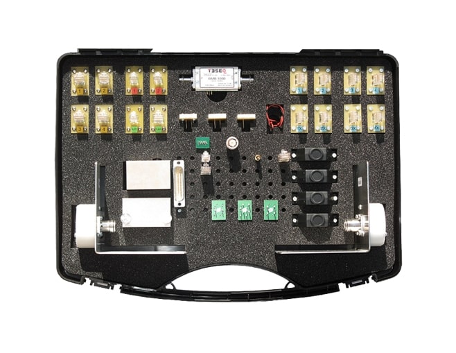
The calibration kit CAS ISN is made for function tests and remeasurements on impedance stabilization network (ISN) for unshielded balanced pairs. Measuring parameters are common mode (CM) impedance, phase angle, voltage division factor, decoupling attenuation (isolation) and longitudinal conversion loss (LCL). Impedance stabilization networks (ISN) are defined in CISPR 22 and CISPR 16-1-2. The CISPR 16-1-2 gives additional requirements and provides examples and measurements for the networks. The ITU-T recommendations G.117 and O.9 offers the background knowledge for measurements on symmetrical telecommunication lines.


