

EMC Test Infrastructure Strategy for Reproducing High-Field-Strength and Complex Electromagnetic Environments
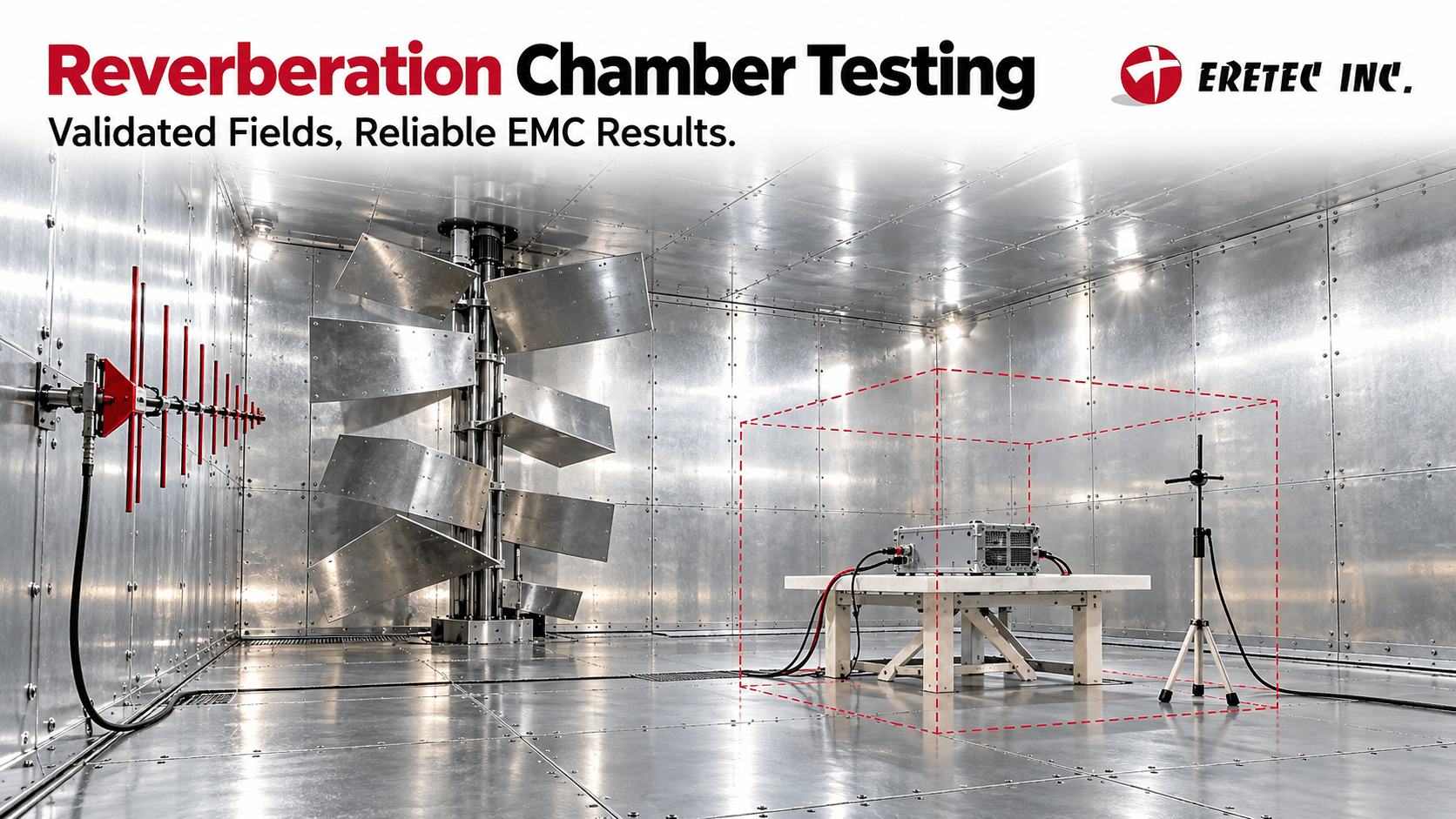
1. Executive Summary
1.1 From Generating High Field Strengths to Reproducing a Validated Test Environment
A reverberation chamber (RC) is not simply a space for generating high radio-frequency (RF) electric fields. The purpose of reverberation chamber testing is to create various electromagnetic field states within a shielded space where repeated reflections occur, statistically evaluate those states, and establish an electromagnetic environment that can be used for actual testing.
IEC 61000-4-21:2011 treats a reverberation chamber as a shielded test environment that uses a tuner/stirrer to vary the internal boundary conditions. RF energy injected into the chamber is repeatedly reflected from the conductive walls, forming multiple resonant modes. As the tuner or stirrer moves and changes the internal boundary conditions, different electromagnetic field distributions are continuously generated. By obtaining and evaluating a sufficient number of these states, a statistically uniform and isotropic test environment that is not limited to a specific direction or polarization can be established.
This principle provides a starting point for understanding the difference between an anechoic chamber or semianechoic chamber and a reverberation chamber. Anechoic and semianechoic environments use RF absorbers to suppress reflections and create a test environment centered on specific directions of incidence and polarizations. In contrast, a reverberation chamber actively utilizes multiple reflections from conductive boundaries and creates various electromagnetic field states through mode stirring. Therefore, the two test environments differ not simply in chamber structure, but in the fundamental principle by which the electromagnetic environment is created.
Differences in Test Environment Generation
| Category | Anechoic / Semianechoic Chamber | Reverberation Chamber |
|---|---|---|
| Basic Principle | Reflection Suppression | Reflection Utilization |
| Main Components | RF Absorbers | Conductive Shielded Enclosure + Tuner/Stirrer |
| Field Generation | Centered on Specific Directions of Incidence and Polarizations | Formation of Various Modes and Field States |
| Test Environment | Controlled Directional Environment | Statistical Field Environment |
| Evaluation Perspective | Electric Field Under Defined Test Conditions | Statistical Characteristics of the Stirred Field |
Research on vibrating intrinsic reverberation chambers (VIRCs) also applies this statistical approach to actual chamber validation. By evaluating the independence, field uniformity, and statistical distributions of electromagnetic fields generated under different chamber states, it is possible to determine whether the test environment is being sufficiently stirred. In other words, what matters in a reverberation chamber is not simply the maximum field strength, but what electromagnetic field states are formed throughout the test space and how reliably they can be reproduced.
1.2 More Important Than High Field Strength Is the Validity of the Working Volume
The fact that the target field strength is measured at a single location inside a reverberation chamber is not sufficient to determine that the entire chamber provides an appropriate test environment. In an actual test, the Device Under Test (DUT) occupies a certain amount of space, so appropriate field characteristics must be ensured throughout the Working Volume in which the DUT is placed.
Chamber Validation under IEC 61000-4-21 is centered on this Working Volume. In a representative validation procedure, the electric field components along the three orthogonal x, y, and z axes are measured at eight locations within the Working Volume. Accordingly, a total of 24 electric field values are evaluated at each frequency, and the statistical variation of these values is used to determine Field Uniformity. Therefore, the performance of a reverberation chamber should be evaluated based not on the maximum field obtained at a specific point, but on the statistical field characteristics throughout the space where the DUT is actually located.
In this process, checking Field Uniformity alone is not sufficient. It is also necessary to examine whether Mode Stirring is effective, whether a sufficient number of independent field states are obtained, and where the Lowest Usable Frequency (LUF) is established. The loading effect caused by placing the actual DUT inside the chamber (DUT Loading) and test Repeatability also affect the reliability of actual test results.
Reverberation Chamber Test Environment Validation Structure
Field Uniformity → Mode Stirring → Independent Samples → LUF → DUT Loading → Repeatability → Actual Test Configuration
In particular, the Lowest Usable Frequency is difficult to determine solely from chamber dimensions or the fundamental resonant frequency. Theoretical calculations are useful for chamber design and initial performance prediction, but the actual lower usable frequency limit should be validated by measuring the chamber's stirring performance and the statistical characteristics of the fields. Studies on RC characterization also distinguish between estimates based on theoretical Modal Density and LUF validation based on actual measurements.
The VIRC study by Izzo et al. demonstrates this difference through actual testing. The VIRC was approximately 26 × 8 × 6 m in size, and its characteristics were evaluated for a 15 × 4.5 × 4.5 m Working Volume. Based on the fundamental resonant frequency, approximately 120 MHz was calculated as an initial reference frequency. However, after evaluating actual statistical characteristics such as independent samples and Field Uniformity, approximately 300 MHz was determined to be the practical LUF. This demonstrates that the frequency predicted by calculation and the frequency that can actually be used after validation do not necessarily coincide.
Perspectives on Reverberation Chamber Performance Evaluation
| Basic Performance Check | Actual Test Environment Validation |
|---|---|
| How high is the maximum field strength? | Is the entire Working Volume uniform? |
| What is the theoretical LUF? | What is the LUF validated through actual measurements? |
| Does the stirrer move? | Does it generate sufficiently independent field states? |
| Does the empty chamber meet the requirements? | Is the test environment still valid with the DUT present? |
| Can the test be performed? | Can repeatable results be obtained? |
Therefore, when constructing a reverberation chamber, performance criteria should address not only "how high a field strength can be generated," but also "from what frequency, over what volume, and under what DUT conditions a validated test environment can be provided."
1.3 Building a Reverberation Chamber Means Building a Measurement System, Not Simply Purchasing a Chamber
A reverberation chamber test facility is not completed simply by installing a Chamber, Stirrer, Power Amplifier, and Field Probe as separate components. In actual testing, every process—from RF signal generation and field generation to DUT status monitoring, data acquisition, and result analysis—must be connected as a single Measurement Chain.
IEC 61000-4-21 likewise does not treat a reverberation chamber simply as a test space. It defines Test Equipment, Chamber Validation, Testing, and Test Results and Test Report as parts of a continuous test methodology. Therefore, when constructing reverberation chamber infrastructure, the design should include not only the hardware used to generate RF fields, but also instrumentation for measuring electric fields and RF power, systems for controlling the stirrer, monitoring equipment for checking the functional status of the DUT, and systems for recording and analyzing data.
Reverberation Chamber Measurement Chain
Signal Generation → Power Amplification → Field Generation → Mode Stirring → Field Monitoring → DUT Monitoring → Data Acquisition → Validation → Analysis → Test Report
The stages in this structure are not independent of one another. The output set at the signal generator is delivered to the antenna through the power amplifier and transmission path, while the electric field inside the chamber is formed through multiple reflections and mode stirring. The resulting field must be verified using field probes and the receiving system, while the functional status of the DUT and any abnormal phenomena must be recorded simultaneously. The measurement data and test conditions must then be analyzed and retained together so that the same procedure can be repeated and the test results can be traced.
This integrated structure becomes even more important for large DUTs. In NASA's reverberation chamber radiated emissions testing of an entire remotely controlled aircraft, the transmit path, receive path, and chamber were calibrated, while computer-based data acquisition and remote control were used during the test process. Telemetry and video/audio monitoring for checking the status of the aircraft were also included in the test configuration. This case demonstrates that a reverberation chamber for large DUTs is operated not simply as an RF-shielded space, but as an integrated test system combining test environment generation, instrumentation, DUT monitoring, and data processing.
Reverberation Chamber Infrastructure Components
| Area | Main Components | Role |
|---|---|---|
| Field Generation | Signal Generator, Power Amplifier, Transmit Antenna | Generate and Inject Target RF Energy |
| Field Formation | Shielded Chamber, Tuner/Stirrer | Multiple Reflections and Mode Stirring |
| Instrumentation | Field Probe, Receive Antenna, RF Instrumentation | Verify Electric Field and RF Characteristics |
| DUT Monitoring | Video, Audio, Optical Communication, Telemetry, etc. | Monitor Functional Status and Abnormal Phenomena |
| Control | Stirrer and RF Equipment Control System | Control Test Conditions and Test Sequence |
| Data | Data Acquisition and Analysis System | Record and Analyze Measurements and Test Status |
| Validation & Reporting | Validation Procedures, Test Report | Ensure Test Environment Validity and Result Traceability |
In summary, the objective of constructing a reverberation chamber is not merely to obtain a chamber capable of generating high field strengths. Rather, it is to establish a Measurement Chain capable of generating the target field, validating the environment, measuring the DUT response, and tracing all test conditions and results. From this perspective, designing the chamber structure, RF power system, stirring system, instrumentation and monitoring, automation, and data management systems as a single test infrastructure is the starting point for reverberation chamber implementation.
2. Why EMC Testing Is Changing
2.1 The Complexity of Electronic Systems Requires Validation of the Test Environment Itself, Not Just the Test Equipment
Modern electronic systems do not operate through a single component or a single signal path. Multiple electronic devices, sensors, communication modules, power systems, and cables are interconnected, and externally applied RF energy couples into the actual electronic circuitry through the antenna, chamber, and structure of the Device Under Test (DUT). Therefore, it is difficult to determine the electromagnetic environment actually experienced by the DUT solely from the output values of the Signal Generator or Power Amplifier.
During testing, RF energy passes through multiple stages and is affected by different physical quantities and conditions.
RF Source Output → Antenna Input → Chamber Field → Working Volume Field → DUT Coupling
The values at each stage are not identical. Losses in cables and connections, antenna characteristics, resonances and reflections inside the chamber, stirring conditions, and the position and structure of the DUT all affect the electromagnetic energy that actually couples into the DUT.
This is also why IEC 61000-4-21:2011 specifies a separate Chamber Validation procedure. The standard does not treat a reverberation chamber merely as a test space, but as an environment that must be validated to determine whether it produces an electromagnetic environment suitable for actual testing. The chamber characteristics and stirring performance must be verified, and the Field Uniformity of the Working Volume used for testing must be evaluated.
The comprehensive review by Yousaf et al. also explains the limitations of determining the Lowest Usable Frequency (LUF) solely from theoretical Modal Density. Determining the actual characteristics of a reverberation chamber requires Characterization that evaluates multiple parameters together, including measured Field Uniformity, Q-factor, Chamber Loss, and stirring conditions.
Parameters to Be Verified in EMC Testing
- RF Generation
- Signal Generator Output, Frequency, Modulation Conditions
- RF Amplification & Transmission
- Amplifier Output, Cable and Connection Losses
- Chamber Excitation
- Antenna Input Power, Antenna Characteristics
- Test Environment Generation
- Reflections, Resonant Modes, Stirring Conditions
- Working Volume
- Field Uniformity, LUF
- DUT Coupling
- Structure, Cables, Position, Loading Effects
- Functional Evaluation
- Actual DUT Abnormalities and Malfunctions
Therefore, modern EMC testing does not end with confirming that the equipment operates according to its settings. It is also necessary to validate what kind of electromagnetic environment the energy generated by the equipment creates within the actual test space and how that environment couples into the DUT.
2.2 Automotive Electrification Is Turning Reverberation Chamber Testing into a Practical Industrial Test Challenge
Automobiles are evolving from mechanical systems into platforms in which electrical and electronic systems and software are closely integrated. Vehicles contain complex arrangements of Electronic Control Units (ECUs), sensors, communication modules, radar, cameras, power electronics, and numerous Cable Harnesses.
In this environment, automotive EMC issues are difficult to explain solely in terms of the characteristics of an individual electronic module. This is because external electromagnetic fields can couple into electronic equipment through the vehicle structure and cables, and the resulting effects may appear as changes in actual vehicle functions.
Electronic Module → Cable Harness → Vehicle Structure → RF Coupling → Functional Response
Cable harnesses, in particular, can serve as important coupling paths in automotive EMC. Previous studies on radiated immunity testing of automotive electronic equipment have repeatedly addressed how electromagnetic energy coupled into cables can be associated with equipment malfunctions.
Bule Mbo et al. compared the electromagnetic coupling characteristics of near-field immunity testing for On-board Transmitters with testing in a Mode-Stirred Reverberation Chamber (MSRC). The study evaluated the radiated immunity of automotive electronic equipment by comparing near-field testing based on ISO 11452-9 with reverberation chamber testing based on ISO 11452-11.
In a Chrysler study by Slattery et al., a reverberation chamber was configured for immunity testing of automotive electronic equipment over the 200–1,000 MHz range. During testing, transmit and receive RF power, the x, y, and z electric field values measured by a three-axis Field Probe, and Stirrer positions were recorded. The test environment was also operated by adjusting the transmit power to achieve the target field strength.
Factors to Consider in Automotive EMC Testing
- Electronic Systems
- ECUs, Sensors, Communication Modules
- Perception Systems
- Radar, Cameras
- Power Systems
- Inverters, Power Electronics, Battery Systems
- Coupling Paths
- Cable Harnesses, Vehicle Body Structure
- Test Environment
- Field Strength, Direction, Polarization, Resonance
- Evaluation Targets
- Electronic Equipment Status and Vehicle Functions
As automotive electrification advances, EMC testing needs to expand from simple component immunity verification toward system-level evaluation that considers vehicle structures, wiring, and functional states together.
2.3 ADAS Testing Must Reproduce Both Electromagnetic and Functional Scenarios
In EMC testing of Advanced Driver Assistance Systems (ADAS), simply applying an RF field to a vehicle is not sufficient. Functions such as Adaptive Cruise Control (ACC), Lane Keeping Assist System (LKAS), and Traffic Sign Recognition (TSR) operate while sensors such as radar and cameras perceive the external environment and the corresponding functions are activated.
Therefore, evaluating the electromagnetic immunity of ADAS requires not only an RF environment but also perception inputs and operating scenarios that allow the vehicle to perform its actual functions.
In a 2024 study by Zhang et al., a Millimeter-Wave Radar Simulator and Visual Projection were used to activate ADAS functions inside a reverberation chamber. This enabled electromagnetic immunity testing to be performed while functions such as ACC, LKAS, and TSR were active.
ADAS EMC Test Environment
Field Scenario → Vehicle Functional Scenario → DUT Monitoring
The study also evaluated the Field Uniformity of the reverberation chamber before testing. Empty conditions without a vehicle and Loaded conditions with a vehicle present were compared over the 80 MHz–2 GHz range, and field strengths outside and inside the vehicle were measured under a target field condition of 36 V/m. The experiments showed a significant increase in the electric field inside the vehicle in the 80–100 MHz range due to Local Resonance.
This case demonstrates that ADAS EMC testing must satisfy three conditions simultaneously.
- Electromagnetic Environment
- Target RF Field and Field Uniformity
- Functional Environment
- ADAS Activation Through Radar and Visual Inputs
- Status Monitoring
- Functional Abnormalities, Warnings, and Malfunctions
Therefore, for function-oriented electronic systems such as ADAS, the test configuration must be capable of evaluating not simply "whether RF was applied," but "how RF affected the system while the actual functions were operating."
2.4 Large DUTs Are Both Test Objects and Factors That Alter the Test Environment
Large DUTs such as vehicles, aircraft, and buses are not simply test objects placed inside a reverberation chamber. Because the DUT itself changes the electromagnetic boundary conditions and loss characteristics inside the chamber, it can also affect the test environment.
When a large DUT is placed inside the chamber, its conductive body, cables, batteries, test benches, and onboard equipment reflect or absorb RF energy. As a result, the chamber's Q-factor, field distribution, and the RF power required for testing may change.
Energy Absorption → Q-factor Change → Field Distribution Change → Required RF Power Change
Therefore, it should not be assumed that the characteristics established in an empty chamber will remain unchanged when the actual DUT is present. IEC 61000-4-21 distinguishes between Chamber Validation and actual EUT test conditions and includes procedures that take into account the reverberation chamber test environment and loading effects.
In the study by Zhang et al. involving an actual vehicle, Field Uniformity also differed between the empty chamber and the chamber with the vehicle present. From 80–280 MHz, Field Uniformity under the Loaded condition was relatively worse than under the Empty condition, whereas from 280 MHz–2 GHz, the results under the Loaded condition were actually better.
Effects of DUT Loading
- Vehicle Body / Large Metallic Structures
- Changes in Reflection and Resonance Conditions
- Cable Harnesses
- Changes in RF Coupling Paths
- Batteries / Electronic Equipment
- RF Energy Absorption
- Test Benches / Auxiliary Equipment
- Changes in Chamber Loss and Field Distribution
- Overall DUT Volume / Geometry
- Changes in Working Volume and Stirring Characteristics
The important point is that the effects of DUT Loading cannot be described as a simple one-directional change, such as merely "reducing the field" or "degrading uniformity." The direction and magnitude of the effects may vary depending on frequency, DUT structure, and the modal state of the chamber, so they must be verified under the actual test configuration.
2.5 Anechoic Chambers and Reverberation Chambers Create Test Environments in Different Ways
Anechoic chambers and reverberation chambers are both used for EMC testing, but the fundamental principles by which they create electromagnetic environments are different.
An anechoic chamber uses RF absorbers to reduce reflections from the chamber walls and applies electromagnetic fields to the DUT with relatively controlled directions of incidence and polarizations. In contrast, a reverberation chamber utilizes multiple reflections from conductive boundaries and statistically creates an electromagnetic environment with various directions and polarizations by varying the resonant modes and boundary conditions using a tuner or stirrer.
Test Environment Generation Methods
| Category | Anechoic Chamber | Reverberation Chamber |
|---|---|---|
| Internal Surface | RF Absorbers | Conductive Boundaries |
| Reflections | Suppressed | Actively Utilized |
| Field Generation | Centered on Specific Directions and Polarizations | Statistical Environment with Multiple Directions and Polarizations |
| Main Mechanism | Reflection Suppression | Multiple Reflection + Mode Stirring |
| Evaluation Approach | Deterministic Test Conditions | Statistical Field Characteristics |
The process can be expressed as follows.
Anechoic Chamber → Absorber → Reflection Suppression → Controlled Direction / Polarization
Reverberation Chamber → Conductive Boundary → Multiple Reflection → Mode Stirring → Statistical Direction / Polarization
The difference between the two test methods does not mean that one is inherently superior to the other. Because they create different electromagnetic conditions, the appropriate method may vary depending on the test objective and DUT characteristics.
Furthermore, testing the same DUT in both environments does not mean that the results will automatically be identical. Fanning's study compared automotive radiated RF immunity test results obtained in an Absorber Lined Shielded Enclosure (ALSE) and a Mode Tuned Reverberation Chamber (MTRC), demonstrating that Correlation between the two methods is a technical issue that must be evaluated separately.
Therefore, when selecting a test environment, the test method should be designed not simply by deciding "anechoic chamber or reverberation chamber," but based on the electromagnetic conditions to be reproduced, the size and functions of the DUT, and the applicable standards and test objectives.
3. How a Reverberation Chamber Works
3.1 Multiple Reflections and Resonant Modes
A reverberation chamber (RC) is a test environment in which radio-frequency (RF) energy is injected into an electrically large conductive shielded enclosure, and multiple reflections from internal boundaries are used to form multiple Resonant Modes. IEC 61000-4-21:2011 treats a reverberation chamber as a structure that varies its internal boundary conditions using a Tuner/Stirrer and creates a statistically uniform and isotropic electromagnetic environment under sufficiently stirred conditions.
When RF energy is injected into the chamber, it is repeatedly reflected from the conductive walls, floor, and ceiling. During this process, multiple resonant modes are formed depending on the frequency and chamber geometry, and the electric field may become stronger or weaker at particular locations. Rather than eliminating these standing waves and resonances, a reverberation chamber uses a tuner or stirrer to continuously vary the boundary conditions and generate different field states.
RF Energy Injection → Multiple Reflection → Resonant Modes → Boundary Condition Change → Multiple Field States → Statistical Evaluation
The comprehensive review by Yousaf et al. summarizes the basic performance of reverberation chambers in terms of Modal Density, Lowest Usable Frequency (LUF), Field Uniformity, and Q-factor. In particular, as frequency increases, the number of modes formed inside the chamber increases, and a larger number of modes generally makes it easier to establish a statistically uniform electromagnetic environment.
Process of Electric Field Formation Inside a Reverberation Chamber
- RF Injection
- Supply RF energy into the chamber through the transmit antenna
- Multiple Reflection
- Repeated reflection from conductive boundaries
- Resonant Mode Formation
- Multiple modes generated according to chamber size, geometry, and frequency
- Boundary Condition Change
- Internal field structure changes through tuner/stirrer movement
- Field State Generation
- Different spatial distributions and polarization states are formed
- Statistical Evaluation
- Multiple states are used to evaluate the uniformity and independence of the test environment
Therefore, what matters in a reverberation chamber is not the field distribution at a particular instant. The performance of the test environment depends on whether a sufficiently diverse range of field states can be generated and statistically evaluated.
3.2 Why Chamber Size Becomes More Important at Lower Frequencies
The low-frequency performance of a reverberation chamber is directly related to chamber size. As frequency decreases, the Wavelength becomes longer, and the number of resonant modes that can be formed within a space of a given size decreases.
Frequency ↓ → Wavelength ↑ → Mode Density ↓ → Greater Difficulty in Forming a Statistical Multimode Environment → Greater Difficulty in Achieving LUF
For this reason, the Geometry and Volume of a reverberation chamber generally have a significant influence on the Lowest Usable Frequency (LUF). A larger chamber can support more resonant modes at the same frequency, making it advantageous for creating a statistical test environment in the lower-frequency range.
However, LUF should not be determined by chamber size alone. The actual usable frequency range of a reverberation chamber is also influenced by the following factors:
- Chamber Geometry
- Q-factor
- Internal Loss
- Stirrer Performance
- Chamber Loading
- Field Uniformity
Pocai et al. experimentally evaluated the LUF of an aluminum reverberation chamber measuring 8.94 × 6.00 × 3.92 m. The initial reference value was approximately 80 MHz, but by loading the chamber and adjusting its Q-factor and field characteristics, the LUF was reduced to 66.76 MHz. This demonstrates that LUF is not a value fixed solely by chamber dimensions, but may vary depending on the actual chamber condition and operating conditions.
Major Variables Affecting LUF
- Chamber Volume
- Larger volume allows more modes to form at lower frequencies
- Chamber Geometry
- Affects mode distribution and modal overlap
- Q-factor
- Affects energy storage and loss characteristics
- Stirrer Design
- Affects modal variation and formation of independent field states
- Loading Condition
- Changes the Q-factor and field distribution
- Field Uniformity
- Serves as a direct criterion for determining the actual usable frequency
In other words, chamber size is an important starting point for LUF, but final performance must be confirmed through actual measurement and validation.
3.3 Mode Stirring — The Purpose Is Not Stirrer Rotation, but Boundary Condition Variation
The purpose of Mode Stirring in a reverberation chamber is not simply to move the stirrer itself. What matters is that the movement changes the electromagnetic boundary conditions inside the chamber and sufficiently alters the resonant mode structure.
Stirrer Movement → Boundary Condition Change → Resonant Mode Structure Change → Different Field States
In the automotive reverberation chamber study by Slattery et al., an asymmetric paddle was used. Received power and field strength varied according to the paddle rotation angle, and the paddle position at which the maximum field occurred also differed depending on frequency. This demonstrates that the role of the stirrer is not simple rotation, but actual modification of the modal structure inside the chamber.
The stirring mechanism does not necessarily need to use a metal paddle. A Vibrating Intrinsic Reverberation Chamber (VIRC) changes the boundary conditions by moving the flexible conductive walls themselves. In the study by Izzo et al., three Linear Actuators operated asynchronously with an amplitude of approximately 50 cm to shake the conductive walls. By avoiding synchronization of the positions and speeds of the actuators, the chamber was configured to reduce repetitive identical states and create more random field conditions.
The VIRC study by Serra et al. also explains that movement of flexible conductive walls can perform the function of mode stirring. Even small changes in the positions of the walls and ceiling alter the resonant modes and standing-wave structure, allowing wall vibration alone to create a statistically uniform field environment.
Representative Mode Stirring Methods
- Mechanical Stirrer
- Changes boundary conditions by rotating a metal paddle
- Tuner Movement
- Changes geometry step by step at defined positions
- Wall Vibration
- Changes boundary conditions by moving flexible conductive walls
- Frequency Stirring
- Generates different modal states by varying frequency
- Source Stirring
- Changes field states by varying transmission conditions
Therefore, a good stirring system should be evaluated not by “how much it moves,” but by “how many different electromagnetic field states it can generate.”
3.4 Independent Samples — The Number of Stirrer Positions Is Not the Same as the Number of Independent Field States
Moving the stirrer to multiple positions does not mean that the same number of statistically independent field states has been obtained. If the fields generated at adjacent stirrer positions are similar to one another, the number of measurements may be large while the actual number of Independent Samples remains small.
Stirrer / Boundary Change → Field Sample Generation → Correlation Evaluation → Independent Field State Determination
IEC 61000-4-21 addresses an approach that evaluates independence using correlation between tuner positions and uses a correlation coefficient of approximately 1/e, or about 0.37 or lower, as a criterion for determining an uncorrelated state.
In a VIRC, because the walls move continuously, field variation can be analyzed over time instead of by stirrer position. Izzo et al. evaluated temporally independent field states using the Autocorrelation Function (ACF) and Coherence Time. The experiment showed the following differences depending on frequency.
- 300 MHz
- Approx. 221 ms
- 1 GHz
- Approx. 51 ms
- 6 GHz
- Approx. 11 ms
The field variation time at 300 MHz was approximately 4.3 times longer than at 1 GHz. In other words, at lower frequencies, the field state changed relatively slowly, while at higher frequencies, independent states were formed at shorter time intervals.
These values were measured in the specific VIRC used in that study and should not be applied as universal values to all reverberation chambers. The number of independent samples and correlation characteristics may vary depending on chamber size, wall movement, stirrer design, and frequency.
3.5 Field Uniformity — The Working Volume, Not a Single Point, Is Evaluated
Field Uniformity is not a concept that represents the entire reverberation chamber with a single value. It is an indicator of how uniformly the electric field is distributed within the Working Volume where the actual test equipment is placed.
In IEC-based chamber validation, the three orthogonal electric field components are measured at multiple reference locations within the Working Volume, and uniformity is evaluated using their statistical variation.
8 Reference Locations × x / y / z Field Components = 24 Field Values per Frequency
Thus, at a single frequency, a total of 24 values are evaluated by combining eight reference locations with three-axis field components.
Field Uniformity is not determined solely by fixed chamber characteristics. In actual testing, the following factors may also influence it.
Frequency → Working Volume → Antenna Position → Stirrer Configuration → Chamber Loading → DUT Geometry
The VIRC study by Izzo et al. also evaluated the actual usable frequency range based on Field Uniformity.
In the vehicle testing study by Zhang et al., Field Uniformity differed between the Empty condition without a vehicle and the Loaded condition with a vehicle present, even in the same chamber. In particular, uniformity was relatively worse under the Loaded condition from 80–280 MHz, whereas the opposite trend appeared at higher frequencies.
Therefore, Field Uniformity is better understood not as a fixed performance value of the chamber itself, but as a performance indicator of the actual test environment, including the specific frequency, Working Volume, antenna, stirrer, and DUT conditions.
3.6 Lowest Usable Frequency — Calculated LUF and Validated LUF Should Be Distinguished
The Lowest Usable Frequency (LUF) is an important performance indicator of a reverberation chamber, but it is not merely a design value defined as “a multiple of the first resonant frequency.”
During the initial design stage, LUF can be predicted using chamber dimensions, resonant modes, and Modal Density. However, in an actual chamber, stirring performance, internal loss, loading, and Field Uniformity also have an influence, so the final usable lower frequency must be confirmed through measurement.
Theoretical Estimate → Chamber Construction → Stirring → Field Measurement → Field Uniformity Validation → Actual LUF
IEC 61000-4-21 treats LUF as the lower frequency at which the reverberation chamber begins to satisfy the operational requirements for testing.
Actual studies also show differences between theoretical and measured values.
- Izzo et al.
- Approx. 120 MHz initial reference → Approx. 300 MHz experimental LUF
- Pocai et al.
- Approx. 80 MHz → 66.76 MHz after Loading
- Bothma et al.
- LUF improved by 4–47 MHz depending on Stirrer design changes
In the VIRC study by Izzo et al., approximately 120 MHz was calculated as an initial reference value from the chamber dimensions and fundamental resonant frequency, but the actual LUF determined after evaluating independent samples and Field Uniformity was approximately 300 MHz.
In contrast, Pocai et al. were able to reduce the initial LUF of approximately 80 MHz to 66.76 MHz through chamber Loading.
A 2025 study by Bothma et al. suggested through simulation that changes in stirrer geometry and surface area could improve LUF by 4–47 MHz depending on the design.
Therefore, reverberation chamber design should distinguish between predicted and validated LUF values. Even if a theoretical value is calculated during the design stage, the final lower usable frequency should ultimately be established through actual chamber field measurements and Field Uniformity validation.
3.7 Working Volume — Chamber Size and Actual Test Space Are Not the Same
The Chamber Internal Volume and the actual Working Volume available for testing in a reverberation chamber are not the same.
Chamber Internal Volume ≠ Working Volume
The Working Volume is the space in which the DUT is actually placed and where the required electromagnetic characteristics must be validated. Because not every location inside the chamber provides the same test performance, a separate volume must be defined with sufficient Clearance from the walls, floor, antenna, stirrer, and other structures.
In the VIRC case studied by Izzo et al., the overall chamber measured 26 × 8 × 6 m, while the Working Volume was defined as 15 × 4.5 × 4.5 m. The field probes were positioned at least 1 m away from the conductive walls or reflective floor. The distance between the transmit antenna and the chamber corner also affected Field Uniformity, and the study maintained a distance of approximately 2 m based on preliminary test results.
Difference Between Chamber Size and Working Volume
- Chamber Internal Volume
- Total physical volume of the shielded enclosure
- Working Volume
- Actual testable region where field characteristics have been validated
- Clearance
- Required separation from walls, floor, stirrer, antenna, and other structures
- DUT Envelope
- Actual occupied space including the DUT, cables, and test bench

Therefore, when designing a reverberation chamber, it is not sufficient to ask simply, “Does the DUT fit inside the chamber?” In practice, it is necessary to determine first whether the space required for the DUT, cables, test equipment, and Clearance can fit within the validated Working Volume.
In other words, the more important question in reverberation chamber design is:
“Can a Working Volume that accommodates the required DUT and Clearance actually be validated?”
Only after this question has been answered can the overall test infrastructure—including chamber dimensions, stirrer placement, antenna position, and RF power system—be designed realistically.
4. Key Testing Challenges
4.1 Field Uniformity — DUT Loading Is Difficult to Explain Based on Physical Volume Alone
Field Uniformity in a reverberation chamber (RC) is not determined solely by the size of the chamber itself or by stirring performance. In actual testing, the Device Under Test (DUT) can interact with the electromagnetic field inside the chamber and alter the existing field distribution.
In this context, there are limitations to evaluating the influence of the DUT solely on the basis of Physical Volume. A 2025 study by Li et al. reviewed the EUT volume criterion presented in IEC 61000-4-21 and pointed out that even EUTs with the same physical volume can affect chamber Field Uniformity differently depending on Electrical Size, Shape, Material, and Internal Structure. In particular, the study demonstrated through simulation that a simple volume ratio may not be sufficient to properly evaluate actual EUT–Cavity Coupling.
Factors Affecting DUT Loading
- Physical Volume
- Physical space occupied inside the chamber
- Electrical Size
- Scattering and coupling characteristics according to DUT size relative to the operating wavelength
- Shape
- Field disturbance depending on flat, slender, three-dimensional, and other geometries
- Material
- Reflection and absorption depending on conductive and dielectric properties
- Internal Structure
- Additional coupling caused by internal metallic components, wiring, and electronic equipment
- EUT–Cavity Coupling
- Actual interaction between the DUT and chamber modes
Therefore, when evaluating Field Uniformity, it is not sufficient to ask only, “What percentage of the total chamber volume does the DUT occupy?” It is also necessary to consider how electrically large the actual DUT is at the relevant frequency, what geometry and materials it has, and how it couples with the resonant modes of the chamber.
4.2 DUT Loading — Empty Chamber Validation and Loaded Test Conditions Must Be Distinguished
Initial chamber validation and actual test conditions with the DUT installed are not the same. In an empty chamber, the chamber’s own Field Uniformity, stirring characteristics, and Lowest Usable Frequency (LUF) can be evaluated under baseline conditions. Once the DUT and test bench are installed, however, chamber loss, Q-factor, and field distribution may change.
IEC 61000-4-21 distinguishes between chamber validation and actual EUT test conditions and structures the test methodology to take loading effects under test conditions into account.
Accordingly, actual implementation and testing require the following process.
Empty Chamber Validation → EUT Installation → Loaded Condition Check → Required Power Adjustment → EMC Test
First, baseline performance is validated in the empty chamber. The DUT, cables, test bench, and auxiliary equipment are then installed, after which the extent to which the existing field characteristics have changed is checked. If necessary, the RF input power must be adjusted to maintain the target field, and this Loaded condition becomes the reference condition for the actual test.
The vehicle testing study by Zhang et al. demonstrates this difference at full-vehicle scale. The study compared Field Uniformity under Empty conditions without a vehicle and Loaded conditions with a vehicle present over the 80 MHz–2 GHz range. From 80–280 MHz, uniformity was relatively worse under the Loaded condition, whereas above 280 MHz, the Loaded condition produced better results.
Distinction Between Empty and Loaded Conditions
- Empty Chamber Validation
- Verify the baseline performance of the chamber itself
- DUT Installation
- Establish the actual test configuration
- Loaded Condition Check
- Verify changes in field characteristics and losses caused by the DUT
- Power Adjustment
- Correct input power to achieve the target field
- EMC Test
- Perform the actual test under validated Loaded conditions
DUT Loading should not necessarily be regarded as a phenomenon that degrades the test environment in only one direction. Because the direction of changes in Field Uniformity or loss characteristics can vary depending on frequency and DUT structure, verification through measurement under the actual test conditions is important.
4.3 Mode Stirring Efficiency — Statistical Independence Matters More Than the Amount of Movement
The performance of Mode Stirring cannot be evaluated by how fast or how much the stirrer moves. The purpose of the stirrer is to vary the chamber boundary conditions and generate field states that are sufficiently different from one another.
Therefore, evaluation of stirring efficiency should consider Stirrer Geometry, Position, Correlation between field states, Independent Samples, Coherence Time, and Frequency Dependency together.
Stirrer Motion → Boundary Change → Field Variation → Correlation Check → Independent Samples
IEC 61000-4-21 presents an approach for evaluating how many independent states are obtained by using electric-field correlation between tuner positions. VIRC studies have also used the Autocorrelation Function (ACF) to analyze the time intervals at which independent field states are formed.
The structure of the stirrer itself can also affect low-frequency performance. In a 2025 study by Bothma et al., changes in LUF were simulated by modifying stirrer orientation, diameter, plate structure, and additional flanges. The results showed that changes in stirrer surface area and structure could improve LUF by 4–47 MHz depending on the design.
Mode Stirring Evaluation Parameters
- Stirrer Geometry
- Whether the geometry produces sufficient modal variation
- Stirrer Position
- Whether the field state changes with position
- Correlation
- How similar the fields are between successive states
- Independent Samples
- How many truly independent field states are obtained
- Coherence Time
- Interval required to form independent states in time-based stirring
- Frequency Dependency
- Whether stirring efficiency varies with frequency
Therefore, the objective of stirrer design is not to create a large number of positions, but to stably obtain as many independent field states as possible within a limited test time.
4.4 RF Power Budget — Amplifier Rated Output and Working Volume Field Strength Are Not the Same
To achieve the target field strength in a reverberation chamber, it is not sufficient to check only the rated output of the Power Amplifier. RF energy passes through multiple devices and transmission paths before reaching the Working Volume and is affected by losses and coupling conditions along the way.
Signal Generator → Amplifier → Cable / Connector Loss → Antenna → Chamber Coupling → Chamber Loss → DUT Loading → Working Volume Field
An amplifier output of 1 kW does not mean that the same amount of power is converted directly into an electric field inside the chamber. Losses occur in cables and connectors, antenna efficiency and chamber coupling characteristics vary, and chamber losses and DUT Loading also affect the final field. These effects may also vary with frequency.
In the automotive reverberation chamber study by Slattery et al., the system monitored values measured by a three-axis Field Probe and adjusted transmit power until the target field of 100 V/m was achieved. The resulting drive power was then used for subsequent tests.
Parameters to Check in the RF Power Budget
- Signal Generator
- Output level, frequency
- Amplifier
- Frequency-dependent output, power margin
- Cable / Connector
- Insertion loss
- Antenna
- Efficiency, impedance, chamber coupling
- Chamber
- Q-factor, internal loss
- DUT Loading
- Additional loss caused by DUT installation
- Working Volume
- Actual target field achieved
Therefore, the RF Power Budget should not be designed around the question, “What wattage amplifier is required?” Instead, the design criterion should be, “How much delivered power is required at each frequency to achieve the target field in the Working Volume under the actual Loaded test condition?”
4.5 Shielding and Interface — The Chamber Boundary Is Both a Structure and an RF System
The Conductive Boundary of a reverberation chamber is not merely an outer wall. It is an element that repeatedly reflects RF energy to create the resonant electromagnetic environment inside the chamber, while also serving as a shielding boundary that separates the test space from the external electromagnetic environment.
Accordingly, interfaces such as the Door, panel Joints, RF connectors, and Feedthroughs should be designed as part of the test environment rather than as auxiliary facilities.
Door → Joint → RF Connector → Feedthrough → Power Cable → Data Cable → Filter → Monitoring Interface → Control Room Connection
This becomes particularly important in large-DUT testing, where power, data, control, video, and telemetry must connect the inside and outside of the chamber, increasing the number of interfaces. These required connections must be provided while maintaining the electromagnetic boundary of the chamber.
In NASA’s full remote-controlled aircraft test, the Chamber and Control Room were configured together with transmit and receive paths, aircraft control, telemetry retransmission, video/audio monitoring, and data acquisition systems. In the reported test configuration, Transmit Path Calibration and Receive Path & Chamber Calibration were also managed as separate procedures.
However, the shielding structures or numerical values used at a specific NASA test facility should not be generalized as universal reverberation chamber design requirements. Because test objectives, facility sizes, and frequency ranges differ, shielding and interface requirements should be designed separately based on the applicable standards and target test conditions.
4.6 Field Monitoring and DUT Monitoring Should Be Designed Separately
In reverberation chamber testing, Field Monitoring and DUT Monitoring answer different questions.
Field Monitoring → “What electromagnetic environment was generated?”
DUT Monitoring → “How did the DUT respond in that environment?”
Field Monitoring records the actual test environment applied to the DUT, including frequency, RF power, field strength, and stirring state. In contrast, DUT Monitoring verifies functional responses such as normal operation, errors, warnings, communication interruption, or sensor malfunction.
The two datasets should be measured separately but linked using the same time, frequency, stirring state, or Test ID. This makes it possible to trace back which field and test conditions were being applied when a specific Failure Event occurred.
In the VIRC study by Izzo et al., three-axis field probe data from the Working Volume were transmitted via optical fiber to an Acquisition System outside the chamber. This allowed field data to be collected while reducing the influence of external electronic equipment on measurements inside the chamber.
In the NASA case, aircraft systems were actually operated while telemetry and video/audio monitoring were used to remotely observe system status during testing.
In ADAS testing, the monitoring scope becomes even broader. In the study by Zhang et al., vehicle functions were activated using a radar simulator and visual projection, after which the status of ACC, LKAS, and TSR functions and any abnormal phenomena occurring during testing were monitored.
Test Data Linkage Structure
- Field Monitoring
- Frequency, RF Power, Field Strength, Stirrer State
- DUT Monitoring
- Functional status, errors, warnings, communication and sensor status
- Scenario Monitoring
- ADAS inputs, radar and visual scenarios
- Common Reference
- Time, Frequency, Test ID, Test Step
Therefore, an automation system should not stop at collecting field data and DUT status data separately. It should be capable of linking them to the same test point and reconstructing them as a single test history.
4.7 Repeatability, Reproducibility, and Correlation Are Different Issues
When evaluating the reliability of reverberation chamber testing, Repeatability, Reproducibility, and Correlation should not be used as if they mean the same thing.
Repeatability refers to the degree to which results remain consistent when the same procedure is repeated in the same test environment. Reproducibility refers to whether similar test results can be obtained under different facilities, equipment, or conditions. Correlation, by contrast, concerns the relationship between results obtained using different test methods, such as a reverberation chamber and an anechoic chamber.
- Repeatability
- Are similar results obtained when the test is repeated in the same environment?
- Reproducibility
- Can similar results be obtained at different facilities?
- Correlation
- What relationship exists between the results of different test methods?
In the study by Musso et al., the same DUT was tested in three reverberation chambers with different characteristics. Repeatability was analyzed using results from multiple configurations within the same chamber, while Reproducibility was evaluated by comparing results from the three different facilities. The study showed that when appropriate RC operating conditions were established, measurement Repeatability and Reproducibility agreed relatively well with the statistical confidence intervals expected for an ideal RC.
By contrast, Correlation between reverberation chamber and Anechoic Chamber (AC) testing is more complex. The Musso study explains that it is difficult to directly equate an AC test using a single direction of incidence with an RC test having omnidirectional characteristics. Under comprehensive AC test conditions that consider multiple incidence angles and polarizations, statistical comparison may be possible for certain DUTs, but such results cannot be generalized to all DUTs.
Fanning’s study likewise points out that although both an Absorber Lined Shielded Enclosure (ALSE) and a Mode Tuned Reverberation Chamber (MTRC) can be used as industrial test methods, their results do not automatically agree and require separate correlation analysis.
Therefore, it is not appropriate to describe the advantage of a reverberation chamber as “providing the same results as all other test methods.” A more appropriate description is that a reverberation chamber forms a statistically defined and validated electromagnetic environment and, under appropriate operating conditions, provides a test method in which Repeatability and Reproducibility can be managed.
5. Reference Test Architecture
A Reverberation Chamber Is an EMC Test System That Integrates Three Infrastructure Layers
A reverberation chamber is not a test facility that is completed simply by installing the chamber body and RF equipment as separate components. In practice, Physical Infrastructure, Measurement Infrastructure, and Digital Infrastructure must be connected within a single test workflow, and the results must lead to Validation and Reporting.
This structure can be understood in connection with the sequence defined in IEC 61000-4-21:2011: Test Equipment, Chamber Validation, Testing, and Test Results / Test Report.
Physical Infrastructure → Measurement Infrastructure → Digital Infrastructure → Validation & Reporting
In other words, the purpose of reverberation chamber infrastructure is not simply to generate an RF field. The overall architecture must physically establish the test space, measure its electromagnetic characteristics, repeatedly execute the test procedure in an automated manner, and connect DUT responses and test conditions within a single data framework.
5.1 Physical Infrastructure
Chamber Structure — Not Simply a Space That Fits the DUT, but a Space in Which the Working Volume Can Be Validated
When designing the chamber structure, the first question should not be whether the DUT physically fits inside the chamber. More importantly, it is necessary to secure the Working Volume required for actual testing and determine whether the required electromagnetic characteristics can be validated within that space.
Accordingly, chamber design should consider the Target Frequency Range, Target LUF, DUT size, Working Volume, Clearance, Stirrer Envelope, antenna location, and interface layout together.
Chamber Structure Design Inputs
- Target Frequency Range
- Overall test frequency range
- Target LUF
- Actual lower usable frequency that must be achieved
- DUT Size
- Size of vehicle, component, or system
- Working Volume
- Actual test region in which field characteristics are validated
- Clearance
- Required distance from walls, floor, stirrer, and antenna
- Stirrer Envelope
- Space required for stirrer movement
- Antenna Location
- Position suitable for field generation and uniformity
- Interface Layout
- Locations for power, data, and control connections
IEC 61000-4-21 uses a chamber validation structure centered on the Working Volume.
In the VIRC case studied by Izzo et al., the overall structure measured 26 × 8 × 6 m, while the Working Volume was separately defined as 15 × 4.5 × 4.5 m. The field probes were also positioned at least 1 m away from the conductive walls and reflective floor. This demonstrates that the entire internal volume does not automatically represent the usable test space.
The comprehensive review by Yousaf et al. also evaluates LUF and Field Uniformity not only in terms of chamber size, but together with characteristics such as Modal Density, Q-factor, and stirring conditions.
The study by Pocai et al. showed that low-frequency performance may vary depending on the actual chamber Working Volume and Loading conditions.
Therefore, the Chamber Structure should be designed not merely as a shielded enclosure, but as a test space in which the Working Volume required for the target DUT and test conditions can be validated.
RF Shielding — Infrastructure for Maintaining the Electromagnetic Boundary
The Conductive Boundary of a reverberation chamber is both a structure that repeatedly reflects internal RF energy and a shielding boundary that separates the test space from the external electromagnetic environment.
Therefore, RF shielding cannot be explained by the chamber walls alone. In actual testing, various interfaces such as doors, panel joints, feedthroughs, power connections, and data connections pass through the chamber boundary, so these elements must be managed as a single system.
Main RF Shielding Design Elements
Chamber Panel → Door → Joint → Feedthrough → Filter → RF Connector → Monitoring Interface
In particular, large-DUT testing requires power supply, data communication, video, telemetry, and control signals to connect the inside and outside of the chamber simultaneously, making interface design more complex.
In NASA’s whole-aircraft reverberation chamber test, transmit and receive paths, remote control, telemetry retransmission, and video/audio monitoring systems were configured between the chamber and the Control Room. This demonstrates that the connection between the shielding boundary and external control systems is a separate infrastructure design consideration in an actual test architecture.
However, it would not be appropriate to generalize the specific shielding performance values or design conditions of that NASA facility as universal RC requirements. In this context, the case is more appropriately used to demonstrate that interfaces become independent infrastructure design elements in large-DUT testing.
Mode Stirrer — A Device for Generating Independent Field States
The role of the Mode Stirrer is not simply to rotate or move. Its purpose is to vary the chamber’s internal boundary conditions, create different field states, and obtain a sufficient number of independent samples.
Geometry → Motion → Field Variation → Correlation → Independent Samples → Uniformity
Changes in stirrer geometry, position, and movement method alter the degree to which the resonant modes change. Therefore, evaluation should focus not on the mechanical movement itself, but on how much the actual field distribution changes.
IEC 61000-4-21 evaluates the tuner/stirrer in connection with the statistical field characteristics of the chamber.
In the VIRC study by Izzo et al., flexible conductive walls were moved asynchronously using linear actuators to generate different field states.
In Slattery’s automotive RC study, electric field and received power characteristics varied according to the angle of an asymmetric paddle.
A 2025 study by Bothma et al. demonstrated through simulation that changes in stirrer orientation, diameter, plate structure, and surface area can affect LUF.
Therefore, the Mode Stirrer should be designed not merely as a mechanical component, but as an electromagnetic performance device for generating independent field states.
5.2 Measurement Infrastructure
Signal Generator / Power Amplifier
The Signal Generator and Power Amplifier form the RF energy source for reverberation chamber testing.
During testing, the required frequency is first set, the required RF level is generated, and the power is then increased through the amplifier to a level that can be delivered to the antenna. During this process, actual delivered power and reflected power should also be monitored.
Frequency Setting → RF Level → Amplification → Forward Power Monitoring
IEC 61000-4-21 treats such RF generation and measurement equipment as part of the Test Equipment.
In Slattery’s automotive RC study, transmit power was adjusted based on values measured by a three-axis field probe to generate the target field of 100 V/m. This demonstrates that RF Power should be operated based on the field actually achieved in the Working Volume rather than solely on the rated output of the Amplifier.
Antenna
The antenna couples the amplified RF power into electromagnetic energy inside the chamber.
RF Power → Chamber Coupling → Multimode Excitation
In a reverberation chamber, sufficiently exciting multiple modes inside the chamber is more important than directly illuminating the DUT from a specific direction. Therefore, the antenna’s position, orientation, and frequency characteristics must also be managed as part of the test configuration.
In the VIRC study by Izzo et al., Field Uniformity changed when the distance between the transmit antenna and the corner of the tent was adjusted. Based on preliminary test results, a distance of approximately 2 m was maintained, demonstrating that antenna position can have an actual influence on Field Uniformity.
Therefore, the antenna should be managed not simply as an RF output device, but as a Configuration element that affects chamber mode excitation and Field Uniformity.
Field Probe / Power Monitoring
The Field Probe and RF Power Monitoring system serve to quantitatively validate the actual test environment.
Their main purposes include:
- Working Volume Validation
- Test Field Monitoring
- Power Calibration
- Loaded Condition Check
IEC 61000-4-21 uses a structure in which Field Uniformity within the Working Volume is measured and the required field under actual test conditions is verified.
In the VIRC study by Izzo et al., three-axis field probes were used at multiple locations within the Working Volume to measure field components, and the measurement data were transmitted via optical fiber to an external Acquisition System.
In the Slattery study, three-axis field probe data and RF Power data were recorded together while the target field was established.
Therefore, Field Probe and Power Monitoring are not merely measurement devices, but core Measurement Infrastructure that links Validation with actual test conditions.
DUT Monitoring
DUT Monitoring is the system used to determine whether the Device Under Test operates normally while the field is being applied.
The monitoring targets may vary depending on the test objective and DUT type.
Functional Status → Communication → Error Code → Voltage / Current → Telemetry → Video / Audio → ADAS Function
For large systems, remote monitoring is important because direct human access inside the chamber may be impossible or may itself affect the test.
In NASA’s whole-aircraft test, telemetry and video/audio monitoring were used to check aircraft status.
In ADAS testing, the monitoring scope becomes broader. In the study by Zhang et al., ACC, LKAS, and TSR functions were activated using a radar simulator and visual projection, and the vehicle was monitored for abnormalities while electromagnetic fields were applied.
Therefore, DUT Monitoring is not merely visual observation, but part of the Measurement Infrastructure that records the functional response of the system under test in real time.
5.3 Digital Infrastructure
Automation and Control — Repeating a Validated Test Procedure in the Same Manner
In reverberation chamber testing, frequency, RF output, stirrer state, field measurement, and DUT status are interconnected. As the proportion of manual operation increases, differences in settings between operators and the possibility of missing records may also increase.
Therefore, the automation system should be designed not merely as a convenience for controlling equipment, but as Digital Infrastructure for repeating the same test procedure and recording all operating states.
Test Configuration → Frequency Setting → RF Power Setting → Stirrer Control → Field Measurement → DUT Monitoring → Event Logging → Next Test Point → Data Storage
In this process, the Test Configuration is first called, followed by frequency and RF Power settings, and then control of the stirrer state. The field and DUT status are measured simultaneously, abnormal events are logged, and the system then moves to the next test point.
In NASA’s test, data acquisition during Transmit Path Calibration and Receive Path & Chamber Calibration was also performed using computer-based systems.
The purpose of automation is not only to increase test speed, but to secure test Repeatability and Traceability by repeating the same settings and procedures.
Data Acquisition & Analysis
Rather than storing data generated during testing separately, it is important to connect them under the same Test ID.
Data to Be Linked Under the Same Test ID
- Test Configuration
- Test conditions and equipment settings
- Frequency
- Applied frequency
- Input Power
- RF input power
- Forward / Received Power
- Transmit and receive RF power
- Stirrer State
- Stirrer position and state
- Field Data
- Electric field measurements
- DUT Status
- DUT functional status
- Failure Event
- Error or abnormal event record
- Timestamp
- Time information for each event
With this structure, when a specific Failure Event occurs, the corresponding Frequency, RF Power, Stirrer Position, Field Strength, and DUT Status at that time can be traced back.
In other words, Data Acquisition is not merely a step for storing measurement values, but a process that connects test conditions and DUT responses within a single data structure.
Report Generation
A Test Report is best designed not as a document created separately after testing, but as the final output of the test data structure.
IEC 61000-4-21 treats Testing, Test Results, and Test Report within the same test methodology framework.
Therefore, the test report should connect the requirements through to the actual measurement results in a traceable structure.
Test Requirement → Validation Record → Test Configuration → Measurement Data → DUT Response → Result
Main Structure to Include in Report Generation
- Test Requirement
- Applicable standard, test frequency, target field
- Validation Record
- Chamber Validation, Working Volume, Field Uniformity
- Test Configuration
- DUT, antenna, stirrer, cables, Loading conditions
- Measurement Data
- RF Power, Field Strength, Frequency
- DUT Response
- Functional status, errors, Failure Event
- Result
- Pass / Fail and test results
The objective of the Reference Test Architecture is not to install the chamber, RF equipment, instrumentation, and control software as separate systems. It is to connect the three Infrastructure Layers into a single validated test workflow.
Physical Infrastructure → Measurement Infrastructure → Digital Infrastructure → Validation → Test → Report
Only when this structure is completed can a reverberation chamber function not merely as a high-field-strength generation facility, but as an EMC test system that validates the test environment, tracks DUT responses, and repeats the same test procedure consistently.
6. Implementation Guide
When implementing a reverberation chamber, it is more appropriate to define the test requirements first and proceed by passing a Validation Gate at each stage than to install the chamber body first and add individual equipment afterward. In particular, IEC 61000-4-21:2011 treats Chamber Validation, Testing, and Test Results / Test Report as a continuous framework. Therefore, the implementation process should also connect design, validation, testing, and documentation within a single workflow.
Step 1. Test Requirements Definition
The first step is to define what DUT/EUT will be tested, under what electromagnetic environment, and by what test method. If the test objective is unclear at this stage, the required chamber size, Working Volume, RF Power, Stirrer configuration, and Monitoring system may all change later.
The main input conditions are the Device Under Test / Equipment Under Test (DUT/EUT), Application, Frequency Range, Target Field, Working Volume, Test Method, and Monitoring Requirement.
Main Inputs
- DUT / EUT
- Size, structure, and cable configuration of the test object
- Application
- Automotive, electronic components, aerospace, ADAS, etc.
- Frequency Range
- Test start and end frequencies
- Target Field
- Required field strength
- Working Volume
- Actual test space that must be validated
- Test Method
- Mode Tuned / Mode Stirred, etc.
- Monitoring Requirement
- DUT status, communication, video, Telemetry, etc.
The Validation Gate is whether the test objective and required electromagnetic environment can be clearly defined in terms of numerical values and test conditions.
The output of this stage is the Test Requirement.
Step 2. Chamber & Working Volume Design
Once the Test Requirement has been defined, the chamber structure and Working Volume are designed accordingly.
The internal volume of the reverberation chamber and the Working Volume are not the same. In actual testing, Clearance must be secured not only for the DUT but also from the walls, floor, Stirrer, and Antenna. Therefore, the overall chamber dimensions must be larger than the Working Volume.
IEC 61000-4-21 uses a structure in which field characteristics are validated based on the Working Volume.
In the VIRC case studied by Izzo et al., the overall structure measured 26 × 8 × 6 m, while the actual Working Volume was defined as 15 × 4.5 × 4.5 m.
Main Review Items
- Chamber Geometry
- LUF
- Working Volume
- Clearance
- Stirrer Area
- Antenna Area
- DUT Access
In addition, as demonstrated by the comprehensive review by Yousaf et al. and the experimental study by Pocai et al., LUF is not determined solely by chamber size. Therefore, Geometry should be considered together with Mode Density, Q-factor, Stirring, Loading, and Field Uniformity.
The Validation Gate is whether the required Working Volume can be secured while accommodating the actual DUT and the necessary Clearance.
The output is Chamber Layout / WV Definition.
Step 3. Shielding & Interface Design
The walls of a reverberation chamber are not merely structural elements, but part of the RF system that forms the Conductive Boundary. Therefore, every Interface connecting the inside and outside of the chamber, such as the Door, Joint, Feedthrough, and Filter, should be managed as a separate design element.
Main Review Items
Door → Joint → RF Connector → Feedthrough → Filter → Monitoring Interface → Control Room Connection
In large-DUT testing in particular, various connections such as power, control, data, video, and telemetry must cross the chamber boundary. These connections should provide the required functions while avoiding excessive disturbance of the electromagnetic boundary of the test environment.
In NASA’s whole-aircraft RC test, transmit and receive paths, remote control, Telemetry, and Video/Audio Monitoring were configured between the chamber and the Control Room. This demonstrates that Interfaces are major design elements in actual large-DUT test infrastructure.
The Validation Gate is whether the required Power, Data, and Monitoring connections can be provided while maintaining the RF Boundary of the test environment.
The output is Interface & Shielding Design.
Step 4. Mode Stirring Design
The purpose of Mode Stirring is not to move the Stirrer a certain number of times, but to generate Field States that are sufficiently different from one another.
Therefore, in addition to Stirrer Geometry, Position / Motion, and Minimum States, the Correlation between actual field states and the number of Independent Samples should also be evaluated.
Stirrer Motion → Boundary Change → Field Variation → Correlation → Independent Samples
IEC 61000-4-21 addresses an approach that evaluates independent states using correlation between tuner positions.
The VIRC study by Izzo et al. analyzed independent field states using ACF and Coherence Time.
A 2025 study by Bothma et al. showed that changes in Stirrer orientation, area, and structure can affect LUF, confirming that Stirrer design can be directly related to low-frequency performance.
Main Review Items
- Stirrer Geometry
- Position / Motion
- Minimum States
- Correlation
- Independent Samples
The Validation Gate is whether sufficiently distinguishable Field States can be generated repeatedly.
The output is the Stirring Dataset.
Step 5. RF Power Chain Design
The target field is not determined solely by the rated output of the Amplifier. RF energy passes through several stages from the Signal Generator to the Working Volume and is affected by losses and coupling conditions.
Signal Generator → Amplifier → Cable → Antenna → Chamber → Working Volume
Therefore, the RF Power Chain should be designed based on whether the required field can actually be achieved in the Working Volume at each frequency.
Main Review Items
- Required Field
- Target field strength
- Cable Loss
- Cable and Connector insertion loss
- Antenna Coupling
- Coupling characteristics with the chamber
- Chamber Loss
- Loss within the chamber itself
- Loading Margin
- Additional loss after DUT installation
- Frequency-dependent Output
- Actual Amplifier output by frequency
In Slattery’s automotive RC, transmit power was adjusted based on the field measured by a three-axis Field Probe to generate the target field of 100 V/m.
In other words, the RF Power Budget should be calculated not from the Amplifier’s wattage alone, but based on whether the actual target Field can be achieved under Loaded test conditions.
The Validation Gate is whether the required target field can be achieved in the Working Volume.
The output is the RF Power Budget.
Step 6. Chamber Validation
Once chamber construction and RF system configuration are complete, Chamber Validation is performed with IEC 61000-4-21 as the primary reference.
At this stage, the Working Volume, Field Uniformity, Stirring, LUF, Chamber Calibration, and Reference Data are systematically verified.
Working Volume → Field Uniformity → Stirring → LUF → Chamber Calibration → Reference Data
IEC 61000-4-21 defines Chamber Validation as a separate procedure and validates the test environment by measuring the field components along three axes at multiple locations within the Working Volume.
As discussed earlier, theoretical LUF can be used as a design reference, but the actual usable frequency range should be confirmed through measurements and Field Uniformity evaluation.
In addition, if changes occur that may affect the test environment, such as significant internal structural modifications, Stirrer changes, or major Interface changes, the scope of Validation should be reviewed again.
The Validation Gate is whether the specified Working Volume is actually usable for testing over the required frequency range.
The output is the Chamber Validation Dataset.
Step 7. Loaded Condition Verification
Even after Validation has been completed in an empty chamber, installing the actual DUT and test bench can change the chamber characteristics.
Therefore, the Empty Chamber Reference and Loaded Condition should be compared before actual testing.
Empty Chamber Reference → DUT Installation → Loading Check → Field / Power Comparison → Test Readiness
The main verification targets include changes in Field Uniformity, changes in Required Power, changes in Q-factor or Chamber Loss, and changes in the test region caused by DUT installation.
In the vehicle study by Zhang et al., Field Uniformity differed between Empty and Loaded conditions depending on frequency. From 80–280 MHz, the Loaded condition was relatively worse, while above that range, the result was actually improved.
This demonstrates that Loading is not a one-directional effect that simply reduces the Field or degrades Uniformity.
The Validation Gate is whether the required test conditions and Working Volume performance can still be maintained after DUT Loading.
The output is the Loading Verification Record.
Step 8. Automation & Control
A Setup that has passed Chamber Validation and Loaded Verification should be automated so that it can be repeated in the same sequence.
In reverberation chamber testing, Frequency, RF Power, Stirrer State, Field Measurement, and DUT Monitoring are interconnected. The more these are managed manually, the greater the possibility of differences in settings and missing records.
Control Sequence
Configuration → Frequency → RF Power → Stirrer → Field → DUT → Failure Check → Next Point → Save
The automation system loads the Test Configuration, sets the Frequency and RF Power, and controls the Stirrer. It then measures the Field and DUT status, checks for Failure Events, moves to the next test point, and stores the data.
In the NASA test, data acquisition during transmit-path and receive-path/chamber calibration was also computer-based.
Therefore, Automation should be designed not merely as a convenience feature, but as a function that secures the Repeatability and Traceability of validated test procedures.
The Validation Gate is whether the same Test Sequence can be repeatedly executed regardless of the operator.
The output is the Automated Test Workflow.
Step 9. Data & Test Report
Saving only Frequency and Field Strength in the final test data is not sufficient to explain the test conditions at the time of the test.
When a specific Failure Event occurs, it should be possible to trace the following relationship in reverse.
Failure Event ← DUT State ← Field Condition ← Stirrer State ← RF Power ← Frequency ← Test Configuration
In other words, it should be possible to reconstruct under which Test Configuration, Frequency, RF Power, Stirrer State, and Field Condition a specific Failure Event occurred.
Final Data Structure
- Test Configuration
- Applicable standard, DUT, test conditions
- Frequency / RF Power
- Applied frequency and power
- Stirrer State
- Position, angle, operating state
- Field Condition
- Field strength and measured values
- DUT State
- Function, communication, Error status
- Failure Event
- Time and type of abnormal event
- Timestamp
- Time synchronization of all data
IEC 61000-4-21 treats Testing and Test Results / Test Report as connected parts of the same test framework. Therefore, the Validation Record, Test Configuration, Measurement Data, and DUT Response should all be traceably linked in the final Report.
The Validation Gate is whether the test conditions and DUT response at the time of testing can be reconstructed from the final Test Dataset and Report alone.
The outputs are:
- Test Dataset
- Chamber Validation Record
- Loading Record
- Test Report
Implementation Roadmap
| Step | Input Conditions | Main Decision | Validation Gate | Output |
|---|---|---|---|---|
| 1. Requirements |
DUT, Test Objective | Frequency, Field, WV | Requirements can be defined | Test Requirement |
| 2. Chamber & WV |
DUT, LUF, WV | Geometry, Clearance | Working Volume secured | Chamber Layout |
| 3. Shielding |
RF, Interface | Boundary, Feedthrough | RF Boundary maintained | Interface Record |
| 4. Stirring |
Chamber, Frequency | Geometry, Motion | Independent Field States secured | Stirring Dataset |
| 5. RF Power Chain |
Target Field | Amplifier, Cable, Antenna | Target Field achieved | Power Budget |
| 6. Chamber Validation |
Completed Chamber | Validation Method | FU, LUF, etc. satisfied | Validation Dataset |
| 7. Loaded Verification |
Actual DUT | Loading Condition | Test performance maintained | Loading Record |
| 8. Automation |
Validated Setup | Control Sequence | Repeatable execution possible | Test Workflow |
| 9. Data & Report |
Measurement Data | Traceability | Test can be reconstructed | Dataset & Report |
The important point in this Roadmap is that each stage becomes an input condition for the next stage. For example, finalizing the Amplifier specification before the Working Volume has been validated, or completing test automation before confirming the Loaded Condition, may reduce the reliability of the overall test system.
Therefore, the implementation process should be managed according to the following structure rather than simply according to the order of equipment procurement.
Requirement → Design → Build → Validate → Load → Verify → Automate → Test → Report
7. Conclusion
The performance of a reverberation chamber cannot be explained solely by its ability to generate high field strengths. In actual EMC testing, the electric field must be generated, multiple field states must be formed, measured, and validated, and then applied to the DUT. At the same time, the DUT response must be monitored, and all test conditions and results must be recorded so that the same test can be reproduced.
This process can be summarized as follows.
Generate → Stir → Measure → Validate → Test → Monitor → Record → Reproduce
The distinguishing characteristic of a reverberation chamber is that it forms a statistical electromagnetic environment by utilizing multiple reflections and mode stirring. However, for that environment to be usable for actual testing, conditions such as Working Volume, Field Uniformity, Independent Samples, LUF, and DUT Loading must also be validated.
For complex systems such as vehicles or ADAS, the chamber itself is not sufficient to complete the test. The RF Power Chain, Field Monitoring, DUT Monitoring, Automation, Data Acquisition, and Test Report must all be connected as part of a single measurement system.
Therefore, what is required for next-generation EMC test infrastructure is not simply a High Field Chamber.
Validated EMC Measurement Environment
In other words, more important than the ability to generate the target field is the ability to measure and validate that electromagnetic environment, maintain test performance under actual DUT conditions, and ensure that test results can be repeated, traced, and reproduced.
From this perspective, a Reverberation Chamber should be designed not as a single chamber product, but as an integrated EMC test system combining Physical Infrastructure, Measurement Infrastructure, and Digital Infrastructure.
8. Appendix
A. Matrix of Major International Standards and References
| Source | Role | Use in This White Paper |
|---|---|---|
| IEC 61000-4-21:2011 | IEC basic EMC standard for RC test methods | RC definition, Test Equipment, Working Volume, Chamber Validation, Field Uniformity, LUF, Loading, Testing, Reporting |
| ISO 11452-11 | RC radiated immunity testing for automotive electronic components | Automotive RC standards framework |
| IEEE Std 1128-1998(R2012) | RF Absorber evaluation | Comparison between Anechoic/Semianechoic environments and RC |
| Izzo et al., 2020 | VIRC Validation | Working Volume, Uniformity, ACF, Coherence Time, Independent Samples, LUF |
| Ely et al., 2011 | Whole-Aircraft RC | Large DUT, Calibration, Telemetry, Monitoring, Control Room |
| Yousaf et al., 2020 | RC Characterization Review | Modal Density, LUF, Q-factor, Field Uniformity |
| Pocai et al., 2006 | Experimental LUF | LUF and Loading / Q-factor |
| Slattery et al., 1998 | Automotive RC | Automotive RC, RF Power, and Field Monitoring |
| Bule Mbo et al., 2022 | Automotive Coupling | Comparison between On-board Transmitter testing and MSRC |
| Zhang et al., 2024 | ADAS RC | Loaded/Empty FU, ADAS activation, internal/external field strength |
| Musso et al., 2003 | RC Repeatability | RC Repeatability, Reproducibility, and comparison with AC |
| Fanning, 2006 | ALSE–MTRC Correlation | Correlation issues between test methods |
| Li et al., 2025 | EUT Loading / FU | Effects of Electrical Size, Shape, and Material |
| Bothma et al., 2025 | Stirrer / LUF | Changes in LUF according to Stirrer Design |
| Serra et al., 2013 | VIRC Structure and Mode Stirring | Explanation of boundary-condition variation and Mode Stirring through movement of Flexible Conductive Walls |
B. Glossary
- Reverberation Chamber (RC)
- A space that uses a conductive shielded enclosure and a Tuner/Stirrer to vary boundary conditions and create a statistical electromagnetic test environment
- Equipment Under Test (EUT)
- Term used in IEC 61000-4-21 for the equipment being tested
- Device Under Test (DUT)
- Term widely used in industry and research literature for the equipment being tested
- Working Volume
- The region in which the required electromagnetic performance has been validated and that is used for actual testing
- Chamber Validation
- The process of measuring and evaluating whether a reverberation chamber satisfies specified test-environment performance requirements
- Mode Tuning
- A method in which the Tuner is moved to discrete positions and the electromagnetic field state is measured at each position
- Mode Stirring
- A method in which the Stirrer is moved continuously while the varying electromagnetic field is measured statistically
- Field Uniformity
- A characteristic representing the statistical variation of electric field distributions measured at multiple locations within the Working Volume
- Isotropy
- A statistical characteristic in which electromagnetic energy is not excessively concentrated in a particular direction or polarization
- Independent Sample
- A measurement sample considered statistically independent because its correlation with other field states is sufficiently low
- Autocorrelation Function (ACF)
- A function used to evaluate correlation between electric fields measured at different times or stirring states
- Coherence Time
- A time scale over which the field state changes by a statistically meaningful amount in a continuous Mode Stirring environment
- Lowest Usable Frequency (LUF)
- The lowest frequency at which the reverberation chamber satisfies the required test conditions and can be used
- Q-factor
- An indicator representing the relationship between electromagnetic energy stored inside the reverberation chamber and its losses
- Chamber Loading
- A phenomenon in which an EUT, test bench, or other structure affects the energy and field distribution inside the chamber
- Chamber Loading Factor
- A factor used to evaluate the effect of the Loaded Condition on the test field and required input power
- Repeatability
- The degree to which test results remain consistent when a test is repeated using the same method and under the same conditions
- Reproducibility
- The degree to which consistency of results is maintained when the test facility, equipment, or conditions are changed
- Correlation
- The relationship indicating the degree to which results obtained from different test methods or test environments correspond to one another
- Traceability
- The ability to verify and reconstruct the relationships among test conditions, frequency, field, DUT status, and test results after the test
C. References
- Bothma, A., Gilmore, J., & Wiid, P. G. (2025). Expanding the lowest usable frequency of reverberation chambers through stirrer design. URSI Asia-Pacific Radio Science Conference (AP-RASC).
- Bule Mbo, C., Klingler, M., Pichon, L., & Bensetti, M. (2022). Analysis of the power coupling between an antenna and a device under test in a MSRC to replace on-board immunity tests of automotive equipment. International Symposium and Exhibition on Electromagnetic Compatibility – EMC Europe.
- Chen, K., Qi, W., Peng, P., Wang, H., Shen, X., Zhao, Y., & Xu, Q. (2023). A hybrid EMC testing facility: Combining transmission line and reverberation chamber measurement system. Applied Computational Electromagnetics Society Journal, 38(1), 15–22.
- Ely, J. J., Koppen, S. V., Nguyen, T. X., Dudley, K. L., Szatkowski, G. N., Quach, C. C., Vazquez, S. L., Mielnik, J. J., Hogge, E. F., Hill, B. L., & Strom, T. H. (2011). Radiated emissions from a remote-controlled airplane—Measured in a reverberation chamber (NASA/TM-2011-217146). National Aeronautics and Space Administration.
- Fanning, C. W. (2006). Achieving correlation of radiated RF immunity testing performed in an absorber lined shielded enclosure and a mode tuned reverberation chamber. IEEE International Symposium on Electromagnetic Compatibility.
- Institute of Electrical and Electronics Engineers. (2012). IEEE Std 1128-1998 (R2012): IEEE recommended practice for radio-frequency (RF) absorber evaluation in the range of 30 MHz to 5 GHz. IEEE.
- International Electrotechnical Commission. (2011). IEC 61000-4-21:2011 electromagnetic compatibility (EMC) – Part 4-21: Testing and measurement techniques – Reverberation chamber test methods (2nd ed.).
- International Organization for Standardization. (n.d.). ISO 11452-11 road vehicles – Component test methods for electrical disturbances from narrowband radiated electromagnetic energy – Part 11: Reverberation chamber.
- Izzo, D., Rommel, A., Vogt-Ardatjew, R., & Leferink, F. (2020). Validation and use of a vibrating intrinsic reverberation chamber for radiated immunity tests. IEEE International Symposium on Electromagnetic Compatibility, Signal & Power Integrity.
- Li, B., Wei, G., Fan, L., Pan, X., Zhao, Z., & Song, L. (2025). Improvement of field uniformity evaluation in reverberation chambers: A simulation-based analysis of EUT volume and uniform region proportion. IET Science, Measurement & Technology, 19, e70026.
- Musso, L., Demoulin, B., Canavero, F., & Berat, V. (2003). Radiated immunity testing of a device with an external wire: Repeatability of reverberation chamber results and correlation with anechoic chamber results. IEEE International Symposium on Electromagnetic Compatibility.
- Pocai, M., Dotto, I., D’Abreu, G., & Festa, D. (2006). Experimental definition of the lowest usable frequency (LUF) of an aluminum made reverberation chamber with reference to the IEC 61000-4-21 standard. IEEE International Symposium on Electromagnetic Compatibility.
- Serra, R., & Rodríguez, A. C. (2013). Vibrating intrinsic reverberation chamber for electromagnetic compatibility measurements. IEEE Latin America Transactions, 11(1), 389–395.
- Sim, D.-U., Kwak, S. I., Kwon, J. H., & Park, S.-O. (2019). Design of new reverberation chamber for electromagnetic compatibility and wireless device measurement applications and its reproducibility performance validation. Microwave and Optical Technology Letters, 61, 801–804.
- Slattery, K., Neal, J., & Smith, S. V. (1998). Characterization of a reverberation chamber for automotive susceptibility. IEEE International Symposium on Electromagnetic Compatibility.
- Yousaf, J., Nah, W., Hussein, M. I., Yang, J. G., Altaf, A., & Elahi, M. (2020). Characterization of reverberation chamber—A comprehensive review. IEEE Access, 8, 226591–226608.
- Zhang, X., Zhang, Y., Chen, D., Fan, Y., Yan, H., & Gao, J. (2024). Research on electromagnetic compatibility validation scheme for ADAS in reverberation chamber. EMC Japan/APEMC Okinawa.